API Tunnels for IoT
 Updated
A common desire is to create a secure tunnel for IoT device communications in order to:
- comply with regional data regulations
- protect against against "man in the middle" (MITM) attacks
- communicate with an on-premise IoT server, an otherwise blocked IoT server, or a mobile IoT platform server
- eliminate DNS and other meta-data leakage
- create quantum-proof data streams
- secure otherwise non-secure API calls
- isolate device management and control channels
- other security or architecture-related considerations
Often, when an organization is concerned about one or more of these issues, it becomes a matter of corporate policy to use a secure tunnel even if every use case does not require it.
This article demonstrates how to use Diode to tunnel IoT APIs for any of those reasons.
Block Diagram
There are four basic components when tunneling IoT communications:
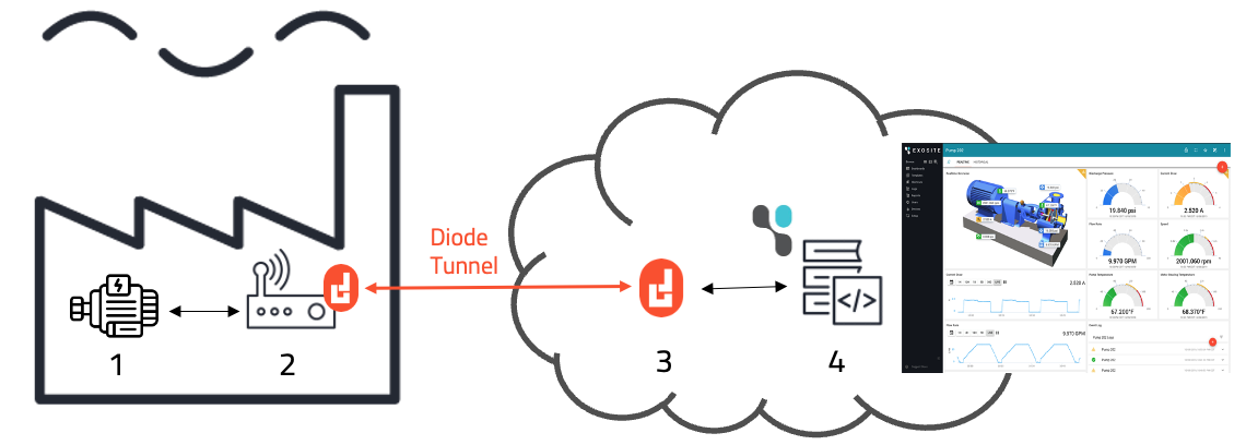
- The IoT Device
Sends data to IoT Server via the tunnel created by the Entry/Exit Nodes - The Entry Node
Establishes a secure tunnel with the Exit Node and sends IoT data to the tunnel. Sometimes the Entry Node is actually located on the IoT Device (as a piece of software). - The Exit Node
Establishes a secure tunnel with the Entry Node and receives IoT data from the tunnel. Sometimes the Exit Node is actually located on the IoT Server (as a piece of software). - The IoT Server
Runs the IoT "Southbound" APIs and receives data from the IoT Device via the tunnel created by the Entry/Exit Nodes. The APIs may or may not also be publicly exposed.
Example IoT Data Tunnel to Exosite's IoT Server
The following example demonstrates how to send tunneled data to Exosite's (exosite.com) multi-tenant IoT Server.
The items below are numbered to correspond to the block diagram above, but actually require that #4 is done first, and #'s 2 and 3 have some inter-related information.
- The IoT Device
Exosite's device API is documented at https://docs.exosite.io/device-connectivity/device-http-api/. We can simulate IoT device calls with curl.
To try this out, you first have to setup an Exosite IoT Connector and provision the IoT Device's identity (jump down to #4 below to do this). Let's assume you've done that and the Exosite IoT Connector's FQDN is: https://a32ktas21gcas0000.m2.exosite.io/ and the IoT Device Client Identification Key (CIK) is 203cd79cfe95d0b4891ef43c73e531d3991fa502.
We use curl's proxy command to send data to a Diode Entry Node (at IP address 192.168.2.101 - the Entry Node is located on the same LAN as the IoT Device):
curl -p 192.168.2.101:1080 -i 'https://a32ktas21gcas0000.m2.exosite.io/onep:v1/stack/alias' -H 'X-Exosite-CIK: 203cd79cfe95d0b4891ef43c73e531d3991fa502' -d 'data_in={"temperature1":42,"pressure1":135.02,"randomnum":122}’ –v
- The Entry Node
The Entry Node in this example is a Linux device, like a Raspberry Pi or other gateway. It has installed the DIode CLI from https://diode.io/download#cli. It is located on the same LAN as the IoT device, and the Entry Node has an IP address of 192.168.2.101.
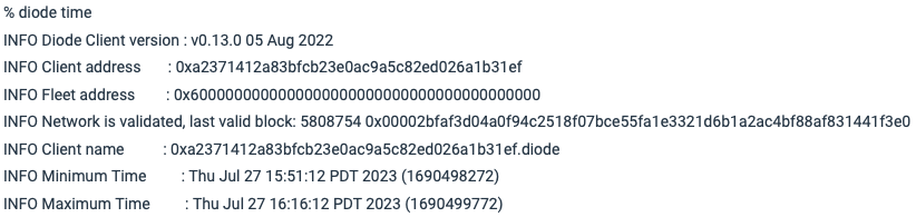
On the Entry Node, use a terminal window to type diode time , and you'll see it print out its Diode Client address of 0xa2371412a83bfcb23e0ac9a5c82ed026a1b31ef. This will be needed in #3 to configure the Exit Node:
We want to forward all traffic from the LAN port 1080 to the Exit Node. We will use the Diode bind command to do that. However, diode -bind only operates on localhost ports, so we have to first create a route from the external LAN port 1080 to the localhost port 1080. We use Linux' iptables to do this:
- First, enable forwarding:
sudo sysctl -w net.ipv4.conf.all.route_localnet=1 - Second, establish the route:
sudo iptables -t nat -I PREROUTING -p tcp --dport 1080 -j DNAT --to 127.0.0.1:1080
Before we can run the bind command, we have to know what Diode Client address to bind it to - we need to know the Exit Node's Diode Client address - jump down #3 to get that (e.g. 0x139ad2e6fsc2377e0f03abc232ea9a83f2eaff371) and then come back here.
Now, it is a simple matter of running the bind command:
diode -bind=1080:0x139ad2e6fsc2377e0f03abc232ea9a83f2eaff371:1080
This command "binds" localhost port 1080 (where all the IoT device data will come to) to the Exit Node's Diode Client address and published port.
- The Exit Node
The Exit Node in this example is also a Linux device, like a Raspberry Pi or other gateway. It has installed the DIode CLI from https://diode.io/download#cli. Since this example proxies SSL traffic, it can be located pretty much anywhere in the world. However, in order to obtain the advantages listed at top, you'll want to be running the Exit Node either on the same LAN as the IoT Server, or in the same data center as the IoT Server (to reduce hops), or in the same region as the IoT Server (to traverse regional firewalls and other security risks).
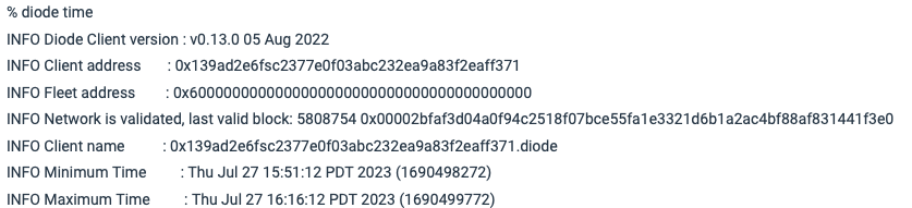
On the Exit Node, use a terminal window to type diode time , and you'll see it print out its Diode Client address of 0x139ad2e6fsc2377e0f03abc232ea9a83f2eaff371. This is needed in #2 above to configure the Entry Node:
We want to create a tunnel with the Entry Node (Diode Client address 0xa2371412a83bfcb23e0ac9a5c82ed026a1b31ef) and send all the data from the tunnel out via a Socks Proxy server egress route. We will use publish -private to create a precisely connected tunnel, and use -socksd to fire up Diode CLI's built-in Socks Proxy server:
diode publish -private 1080:1080,0xa2371412a83bfcb23e0ac9a5c82ed026a1b31ef -socksd
This exposes the Exit Node's Diode Client address and published port precisely ONLY to the Entry Node (0xa2371412a83bfcb23e0ac9a5c82ed026a1b31ef), connects the tunnel to localhost port 1080, and fires up a Socks Proxy server that lives inherently on localhost port 1080.
- The IoT Server
Create an account at https://exosite.io and create an IoT Connector:

Then, add a device by clicking:
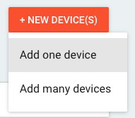
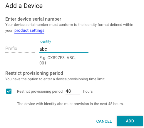
Give it an arbitrary (but unique!) identity and click "Add".
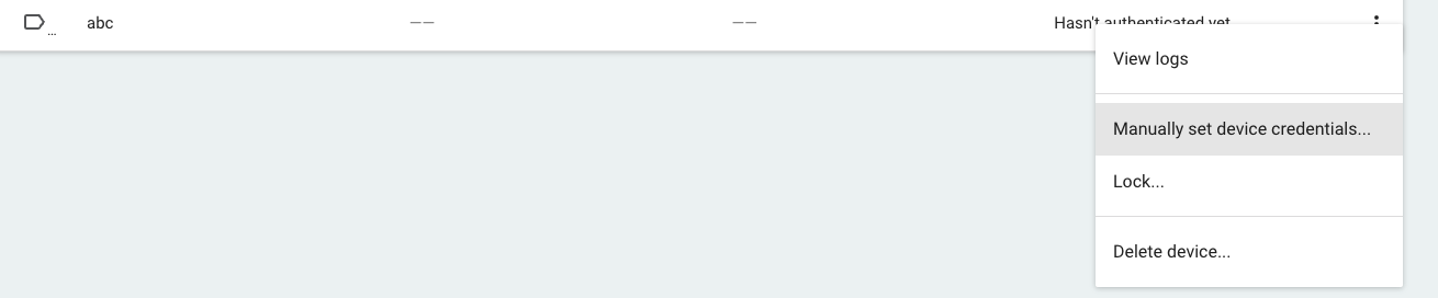
Click the little three-dot menu on the device and click "Manually Set Credentials" (we could auto-provision, but that is an extra step):
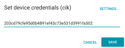
Accept whatever key is given to you - you need that key in #1 above!
Finally, click the "Settings" menu item on the left and copy the IoT Connector's FQDN (e.g. a32ktas21gcas0000.m2.exosite.io) - you'll also need that in #1 above!
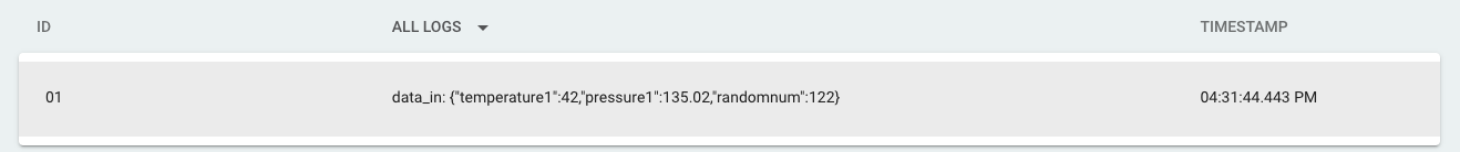
Once that is setup, if you go back up to #1 and execute the curl command, you should be able to go to the Logs menu item and see data flow in!